Weifang Subtor Rotating Precision Machinery Co.,ltd
- Home
- Information
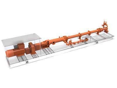
- Progressive Cavity Pump Configuration Options
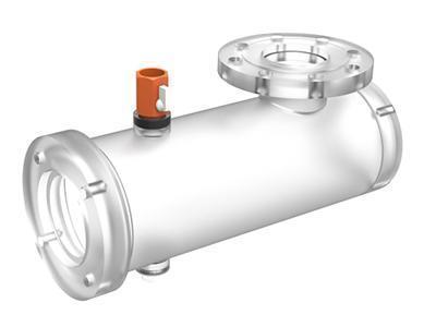
Water Inlet
During use, the dry running can result in catastrophic damage to the stator and rotor in seconds. To avoid this, Subtor has designed a water inlet with a suction chamber. This injects water or other liquids into the pump in order to prevent damage during initial use or when restarting the pump. The water inlet can also be used to exhaust air to ensure the flow of media.
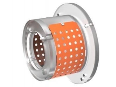
Shield of the coupling shaft
The coupling shaft runs throughout the pumping process. It requires protection, therefore, Subtor has designed a perforated plate shield for the coupling shaft that is easy to remove for maintenance purposes. It helps to avoid damage and make the shaft more visible.
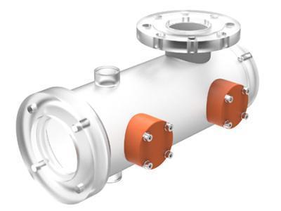
Suction chamber with inspection window (customize)
The universal joint of progressive cavity pumps is located within the inside of the suction chamber. It is a vulnerable component that is difficult to remove and maintain safely. Subtor has made it so that it is visible and easy to find so that it can be repaired with ease. It can be repaired through an inspection window, which can be customized based on your requirements.
Joint (customize)
Besides standard flanged joints, we can create custom joints for customers. The available joints include a screw joint, clamped joint, and quick-release joint. The orientation of the link can also be customized upon request.
Flushing and cooling scheme of mechanical sealing
The flushing and cooling processes of the mechanical sealing of our pumps was carefully developed to provide an improved seal for improved performance and to prolong the service life of the pump.
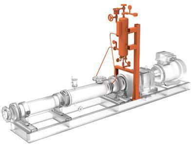
Flushing and cooling scheme of mechanical sealing
As the working conditions require, the skid seat features a brake valve, safety valve, non-return valve, tank, filter, detecting instruments and electrical automatic control system to improve operational simplicity.
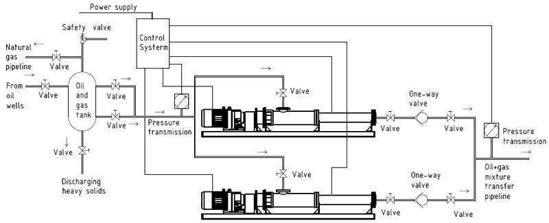
Inlet constant-pressure control
The pressure sensor is installed in the inlet component of the progressive cavity pump to ensure its automatic control over the constant pressure in the system. If the pressure exceeds a set amount, the pump increases its rotational speed in order to regulate the pressure.
Outlet overpressure protection
A pressure sensor is also installed at the outlet end of the pump. When the outlet pressure surpasses the set amount, the pump reduces speed or stops completely to prevent damage.
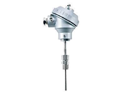
Temperature sensor
The temperature sensor is installed within the stator to monitor the temperature during operation. When the temperature exceeds the limit, a signal will sound and the controlling system will stop the pump to prevent damage.
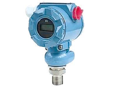
Pressure sensor
The pressure of the outlet end is monitored constantly. The signal is transmitted to the controlling system in real time. The progressive cavity pump will stop itself immediately if the outlet pressure exceeds the preset number.
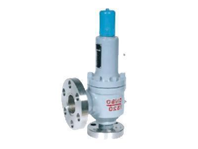
Safety valve
A safety valve is installed at the high pressure end of the outlet. When the outlet pressure increases and exceeds the preset pressure allowance, the valve will open and pour the media into the low pressure end or through the return pipe. This will return the pressure to a safe level.
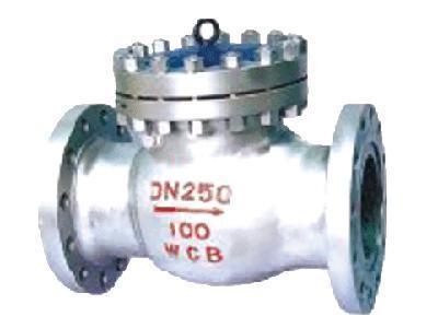
Back-pressure valve
When the pump stops running, the outlet end will experience a higher pressure than the inlet, resulting in reverse pressure to the pump that leads to the rotor. It will cause the motor to rotate backwards. The one-way back pressure valve can isolate media from the outlet end to prevent damage to the pump.